PART 1 – HARDWARE
WARNING:
In this project, We will be dealing with the AC MAINS which can kill you instantly. Observe proper procedures and precautions when dealing with the mains’ electricity.
1. Make sure you removed all your metal jewelries that can accidentally come in contact with the live(hot) or neutral wire.
2. Use only your one hand, preferably wear an insulated glove when dealing with AC mains, put your other hand at your back, so if you accidentally touched the mains it will not flow in to your chest cavity.
3. Always get another person observing you if you are dealing with the mains.
4. Anything above 12V can shock you and 0.50A of current can stop your heartbeat.
CAUTION:
Electrostatic Discharge (ESD)
All microcontroller and digital Integrated Circuit devices are sensitive to ESD, they may be destroyed by it instantly. Before unboxing or removing them in protective anti-static packaging, please ground yourself to a metal chassis or doorknob or wear an anti-static gloves.
I have seen some Wi-Fi controlled AC outlets in Malls but only to find out that they cost about PHP 700~1000 which is about $12~18 US dollars. It would be wise to Do-It-Myself than buying one, I already have a Wemos D1 mini and a BMP180 Barometer and Pressure Sensor but I do not have a relay. The initial design is this:
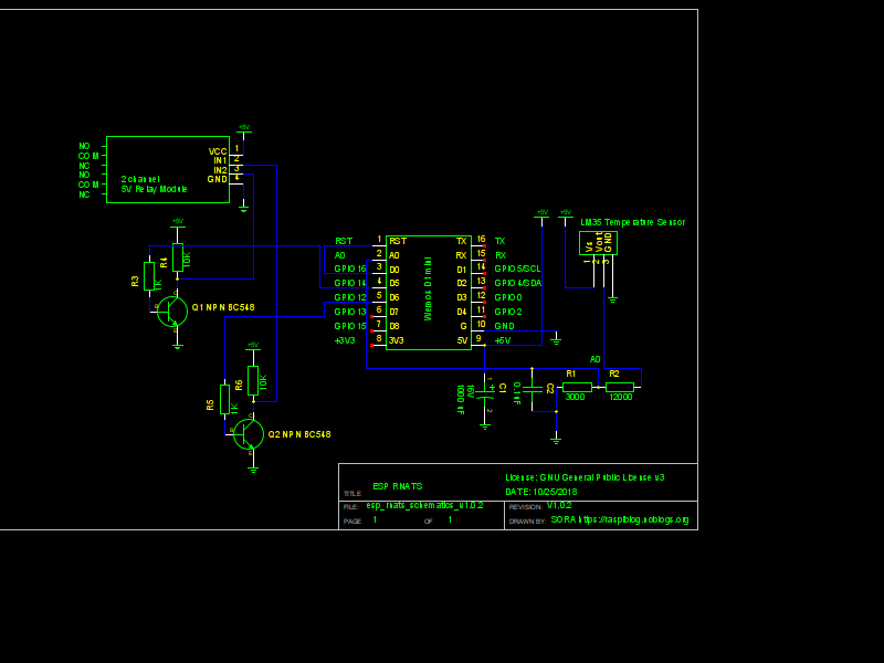
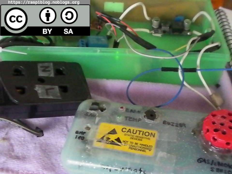
The design uses a 5V LM35 Analog Temperature Sensor and a two channel 5V Relay, the LM35 costs about Php60 and the two channel relay for PHP 120. Resistors costs about PHP 0.50/pc and jumper header wires about PHP 3.0/pc I already have them. In the end I did not purchased the LM35 and the two channel relay. If you want to try to build the design yourself then you are welcome to, I do not have any software implementations for it though. Second option is to use my Portable WiFi Repeater with Sensors as the relay controller, so I purchased a one channel 5v relay rated max of 10A for about PHP 70. Here is the revised design:
ESP_WTCR
The hardware parts for this project and their cost:
– 1x WeMos D1 mini (from my ESP_WNATS project) or an ESP8266 ESP-01 = PHP 350
– 1x 5v 1 ch Relay module = PHP 70
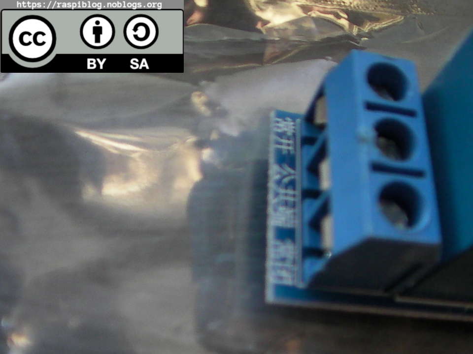
Good isolation in the relay from AC mains (Notice the air gap between the COM and the relay coil input.)
But do not bet your life with this, do not use this when there are thunderstorms.
– 1x BC548 = PHP 3.0
– 1x Resistors (1K, 10K 1/2W) = PHP 1.0
– 1x Prototype Stripboard = PHP 15
– Transformer (from the previous post) = PHP 0
– Bridge Rectifier (from the previous post) = PHP 0
– 1x LM2596 DC Buck Converter Module = PHP 199
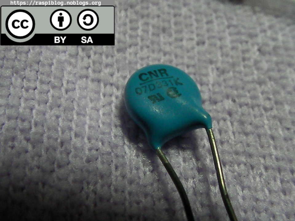
– 1x MOV−07D331K Varsistor (given to me) = PHP 0
– 2x Fuse holder in-line = PHP 30/pc
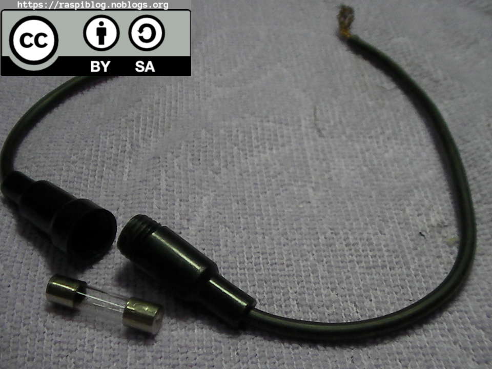
– 1x 0.5A Fuse = PHP 3
– 1x 5A Fuse = PHP 3
– Male to Female Jumper Wires 20cm = PHP 3/pc
– Female to Female Jumper Wires = PHP 3/pc
– 18 AWG 2m Wire = PHP 13/m
– 24 AWG 1m Wire = PHP 7/m
– MicroUSB data + power cable = PHP 10

– 1x BMP180 i2c Sensor = PHP 199
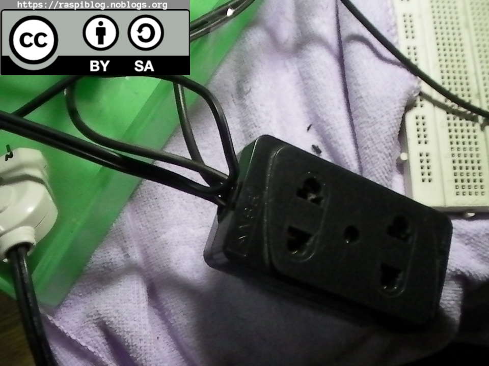
– 1x 10A Type A Male Plug = PHP 30
– 1x 10A Type A Extension Outlet = PHP 35
I have modified my ESP_WNATS to be able to control a 5v single channel Relay based on the environmental temperature. If the temperature is below thirty degrees then it must turn on the Relay which will turn off the electric fan, if the temperature is higher than thirty degrees then it will turn the fan on. I can also turn the relay on or off using the telnet interface.
In the Philippines the AC electricity is rated for 220V, frequency is 60Hz, the outlet can be type A, B or C but in my house it is of type A without grounding. I purchased a cheap extension outlet that has rating of 10A max with two type A plug, a male plug rated max 10A and a 2-meter wire with a diameter of 0.75 square mm and has a label of #18 AWG. The #18 AWG wire is rated for maximum of 5A current based on my reference book. Since my electrical load is only a maximum of 3A, I chose this wire.
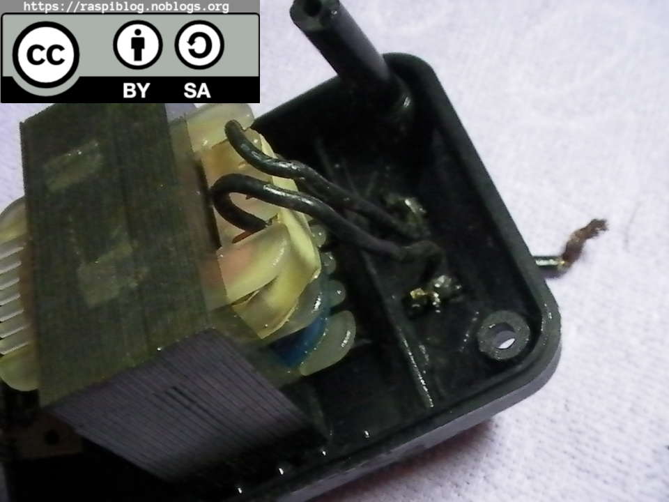
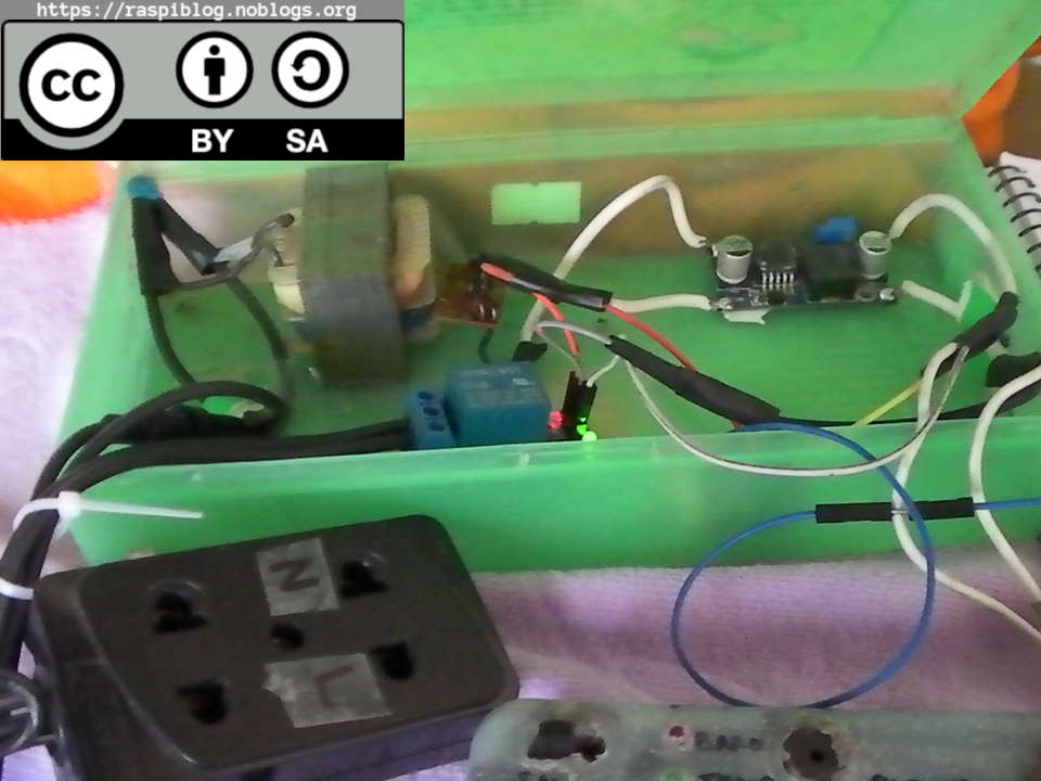
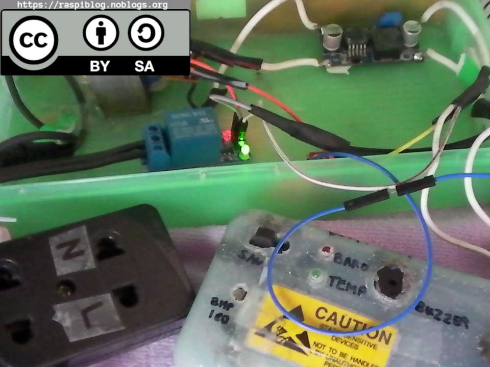
Instead of buying the Hi-Link (HLK-PM01) AC/DC small switching PSU for Php200 I just repurposed the AC/DC Adaptor from my previous post, I used the one with the heavy transformer rated 9.6V and 800mA output DC voltage. I added a transient voltage protection it is a Metal-Oxide Varsistor (MOV) that was given to me years ago. It is a “Bourns Varsistor” rated for max 330V and 150pF, I connected it in parallel with the transformers AC input side. The secondary side with the bridge rectifiers does not have a filtering capacitor, but I forgot to buy some capacitors, so I will just let it be. The voltage output of the bridge rectifier is about 15 Volts it is really unregulated so, I connected a LM2596-ADJ DC Buck Converter Module that is lying around which was used to power the Raspberry Pi 2 Model B but replaced it with MP1584 module.
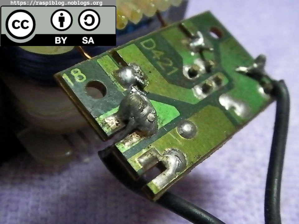
Bridge Rectifier (the solder joint is loose)
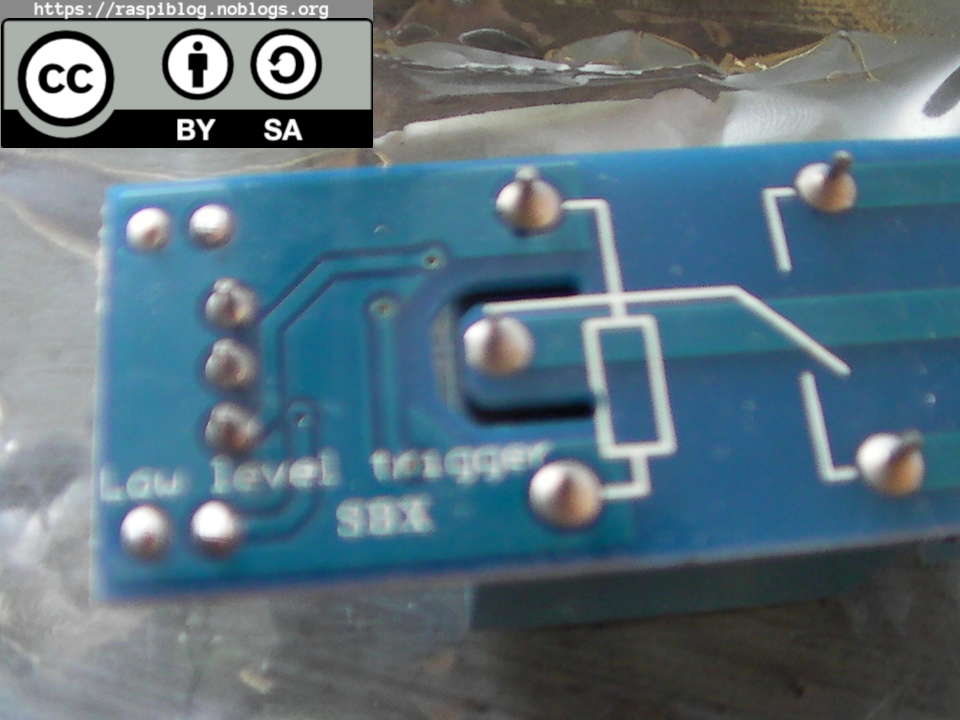
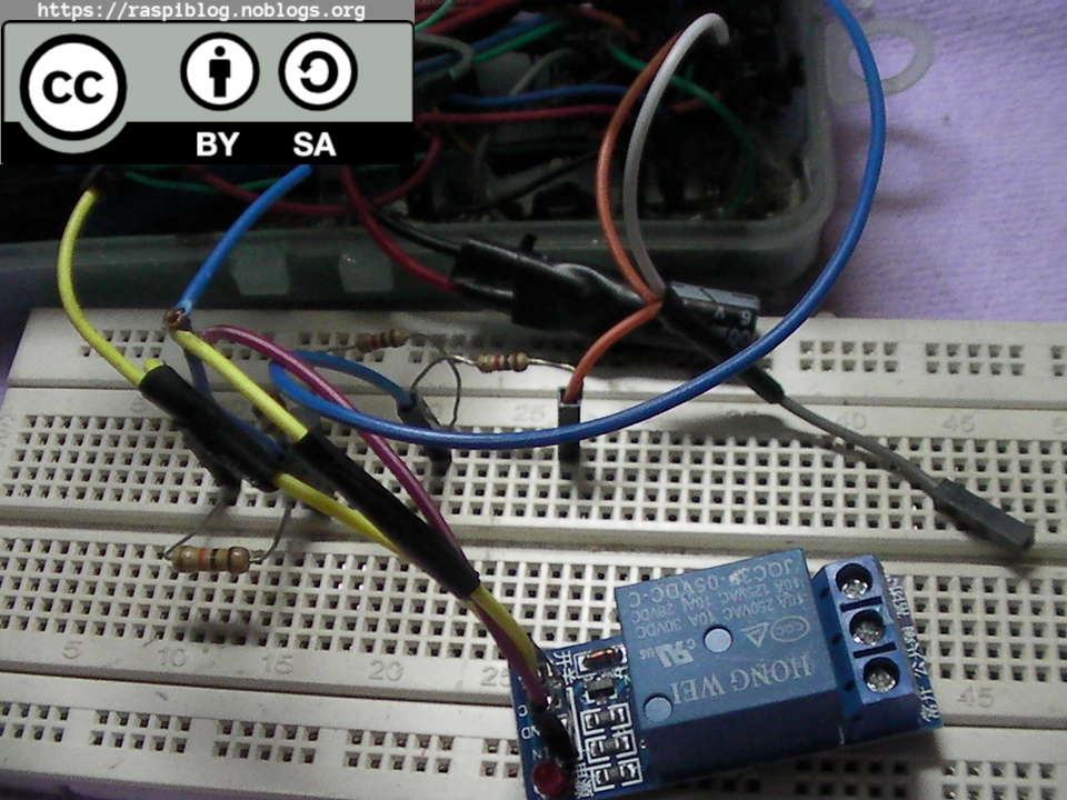
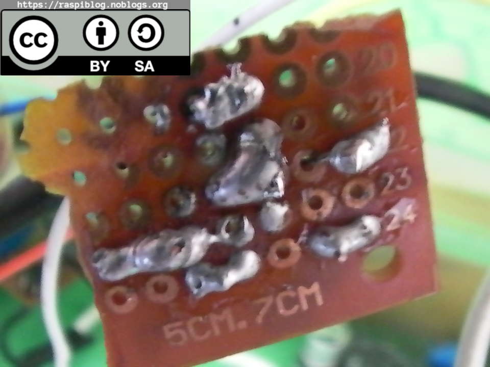
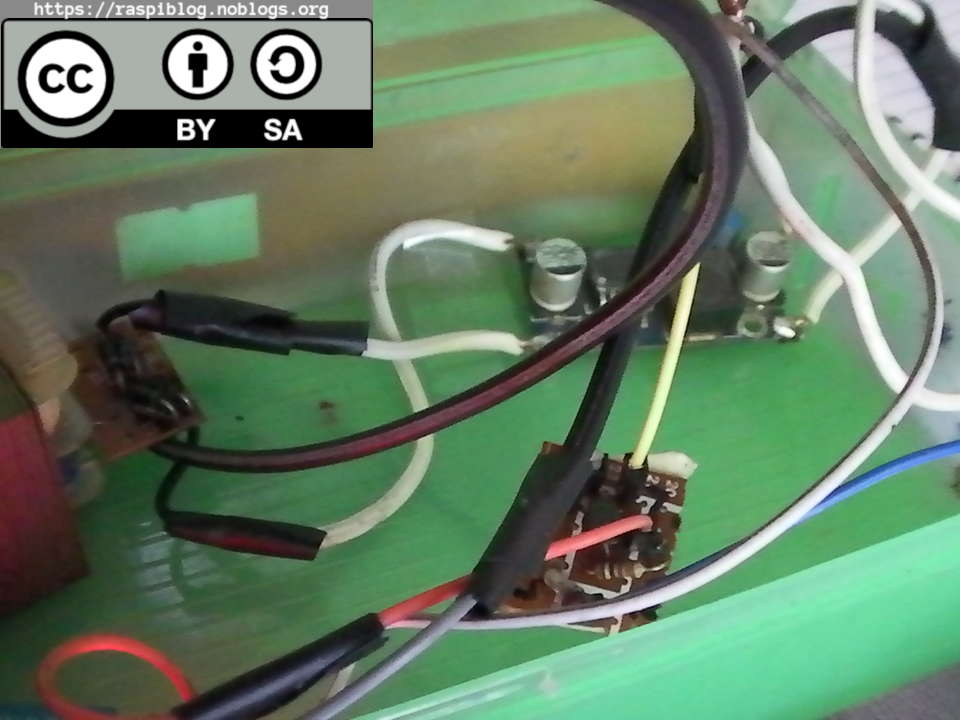
I tried to plug in the relay to the wemos d1 mini GPIO and it does not turn off, it was because the relay is rated for Arduino at 5V and I need to create a driver circuit for it to be used for the ESP8266. I made a small driver with the BC548 an NPN transistor a 1K ohm, 10K ohm 1/4 W resistor and for the jumper header a 2.54mm male header pin. The soldering is not good since I purchased a cheap soldering lead. After soldering it, I tested the board and it worked fine.
Breadboard with the Relay Driver
Soldered Relay Driver
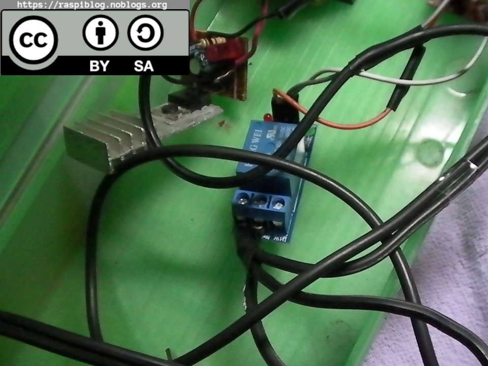
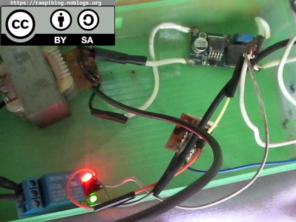
I connected the output of LM2596 to the 5v VCC relay and the 5V input of my PCB relay driver. I also spliced a cheap microUSB data + power cable and connected the output of the LM2596 +Vout and GND to power the Wemos d1 mini.
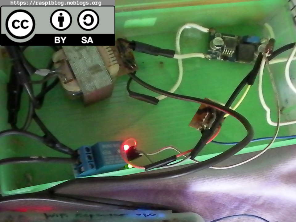
Everything works now, I have not connected the DIY AC extension yet.
WARNING again, we are dealing with the AC mains so be careful! Unplug all adapters or power to the esp8266 and relay before doing the following.
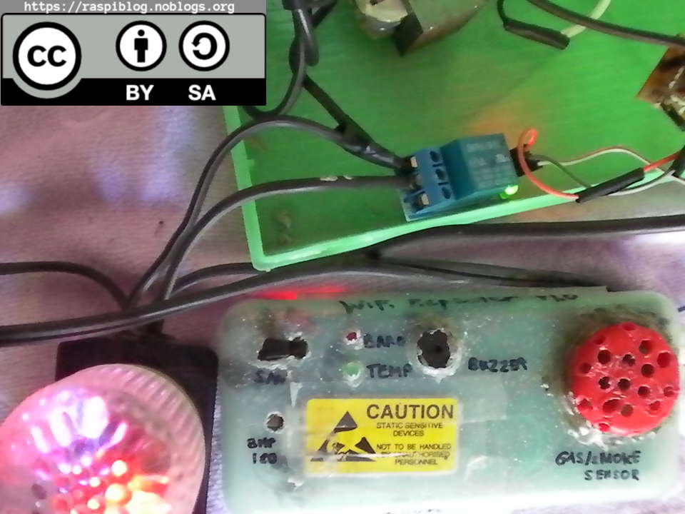
Connect the Live (hot) wire to the COM pin of the Relay and the NO pin to the wire leading to the extension outlet. The only thing to be done is the software part.
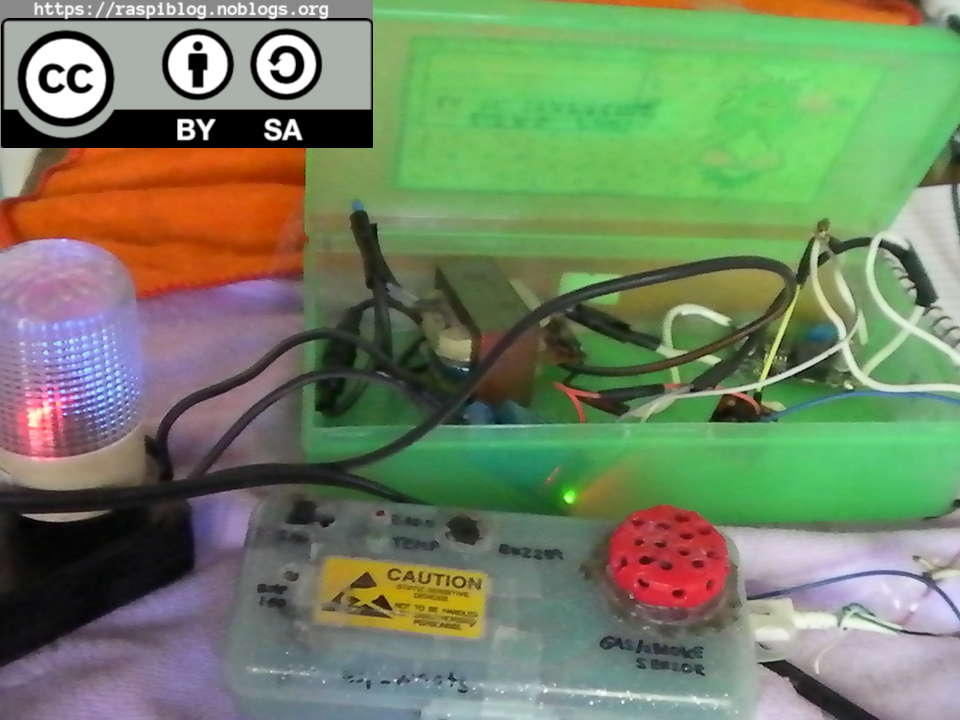
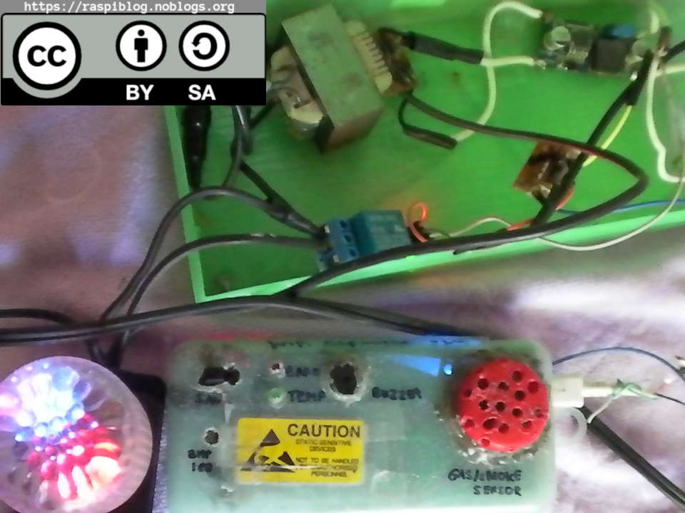
For the casing of the Relay and the transformer I used an old Plastic Pencil case. Since the transformer and the LM2596 module gets hot, you may want to put them in a metal enclosure so the heat will be distributed across the casing. It will act like a heatsink, be careful not to short the pins of the LM2596 module and the relay module.
Note: If you have a switching power supply like a Phone charger with a 5v out, you can use that instead of the heavy transformer and LM2596 that I used here. I also tried to use the LM7805 with a litte heatsink instead of the LM2596 and it got hot to touch, more on this later. Connecting the multimeter in ammeter mode with series to the LM2596 Vout I found out that the entire circuit uses only 0.20A of current, the loads are Wemos D1 mini, MQ-2 5v Gas Sensor, BMP180 and the 5v Relay ON. If the relay is switched off the current becomes 0.16A. I also plan to remove the Green and Red LED since this consumes little current.
If you are going to use this circuit for 24/7, I would not recommend on using cheap power supply (Chinese no-name brand). Instead, use genuine chargers or power supplies that has QC, HiPOT, CE, UL certification (compare the file number to the UL verification website, the file number looks like E123456) and other certification marks appropriate for your country.
The LM7805 regulator is on the left with the heatsink, I assembled it myself. I recycled the heatsink from a broken PC PSU thus reducing e-waste.
The Casing:
Top View
Prototype
Recycled parts:
– AC/DC Adapter (Unregulated DC PSU)
– Plastic Pencil Case
– Heatsink (for LM7805 Module)
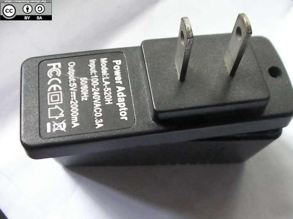
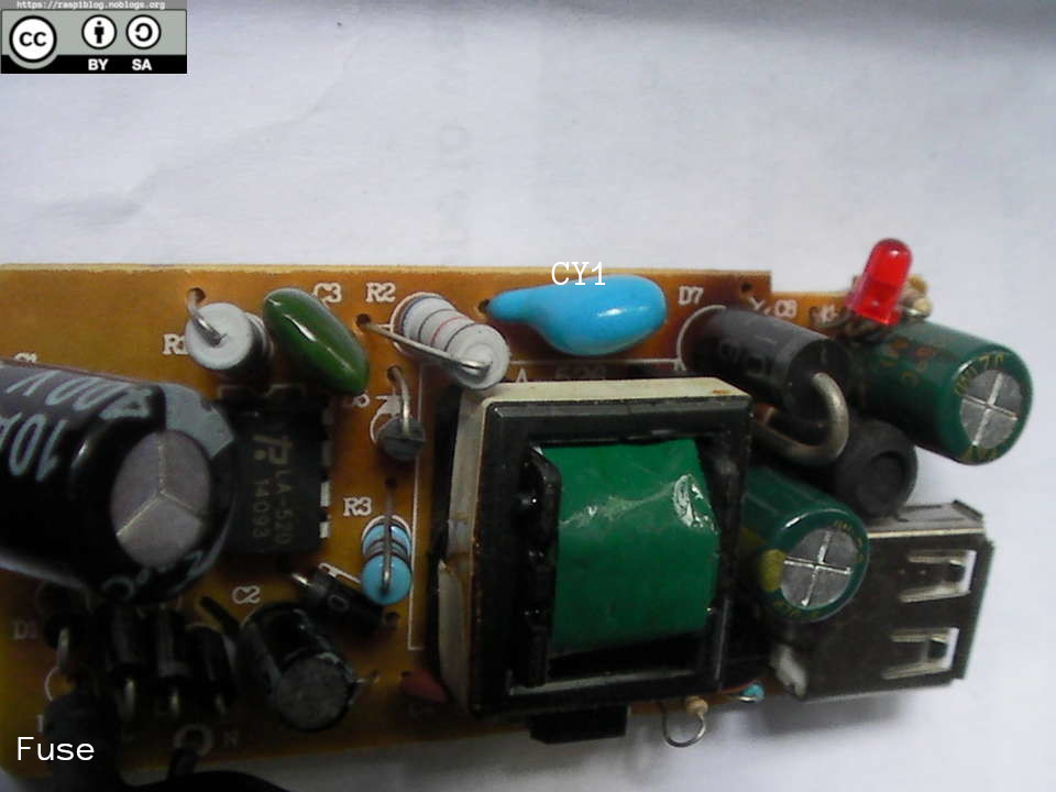
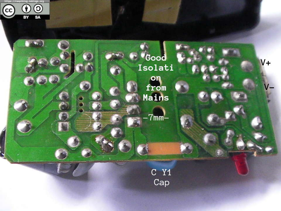
Revision 2 November 01, 2018: Using a Good SMPS as a Power Supply:
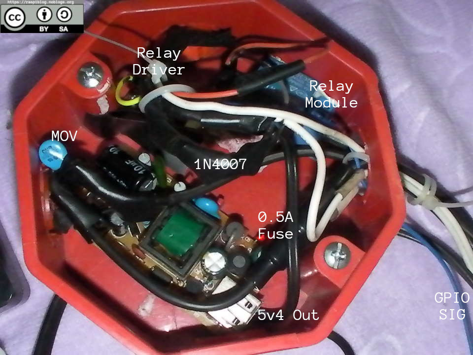
I used my broken Tablet’s Adapter to power my Wemos d1 mini (ESP_WNATS) and Relay. The adapter has good isolation over the mains and has good Class Y1 capacitor. It has a fuse but no inrush current protection or MOV (I added one).
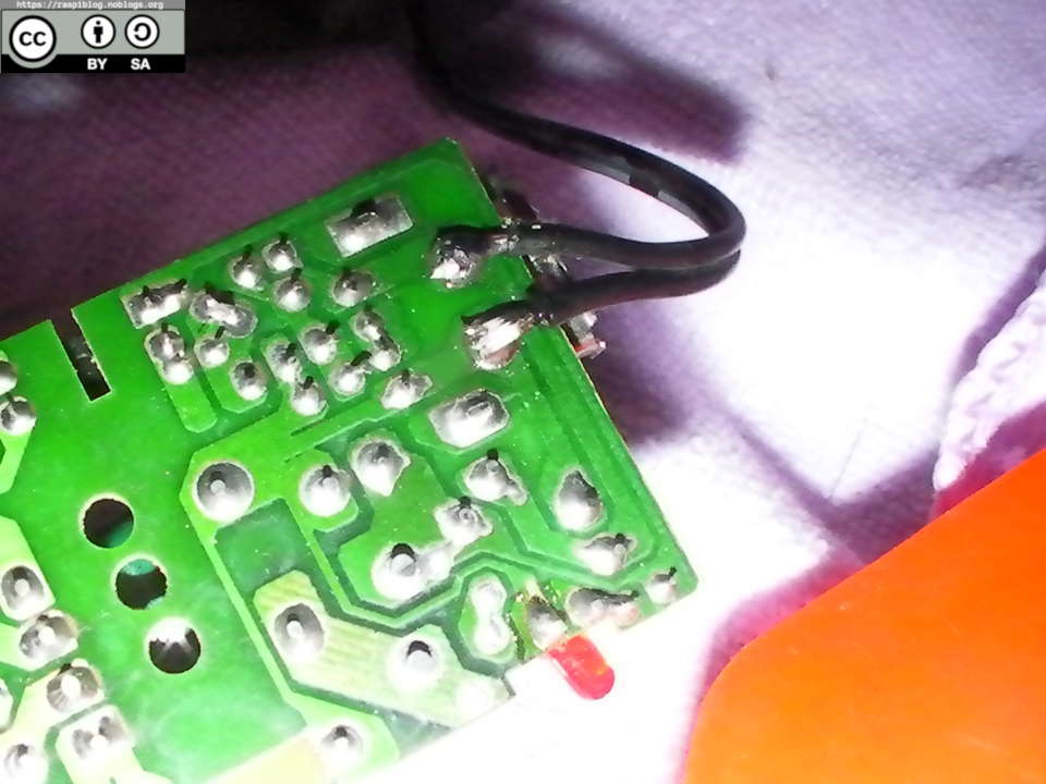
The output voltage is 5.4V, so I used a 1N4007 Diode in series to V+ to reduce the voltage by 0.3V = 5.1V
I put the adapter, relay and realay driver to a electric orange junction box.

Except where otherwise noted, this work is licensed under Creative Commons Attribution-ShareAlike 4.0 International License (http://creativecommons.org/licenses/by-sa/4.0/).
I hope that this post is useful to you, if you liked this post you may support me via liberapay. Thank you for your support.

References:
Scherz, P. (2000). Practical Electronics for Inventors. USA: McGraw-Hill, pp. 283-297.
Passerby. (2017, April 5). How to drive a relay from ESP8266 gpio. Retrieved from https://electronics.stackexchange.com/questions/296330/how-to-drive-a-relay-from-esp8266-gpio