PART 3 — HARDWARE AC/DC Adapters
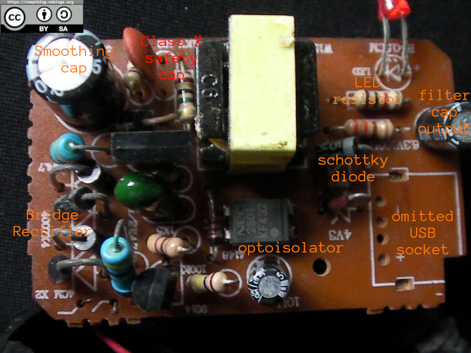
I have reverse engineered the RC Toy Car Charger and the schematic is here:
Disclaimer: I do not guarantee the correctness of the schematic.
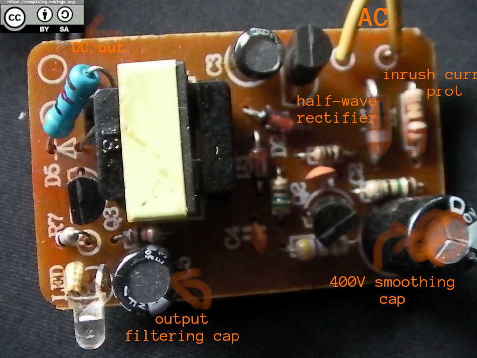
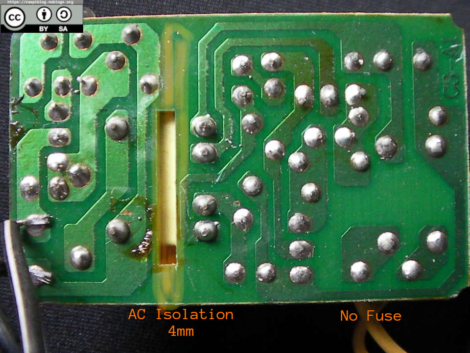
It is a SMPS with a half-wave rectifier (1N4007) but it does not have any transient protection, short circuit (fuse) protections. It smells bad when I operate it like a burning electrical insulation. There is no optocoupler in the board only the transformer, the gap between the mains and the output is about 4mm which close to the 5mm UL recommendation.
The output voltage at no load is about 15V, then with a 10 ohm 10W resistor connected to it, the voltage dropped to about 5V. The current consumption of the resistor is about 0.3A.
PCB front and Back
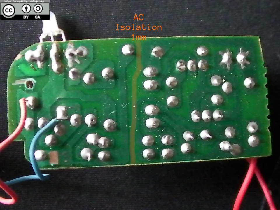
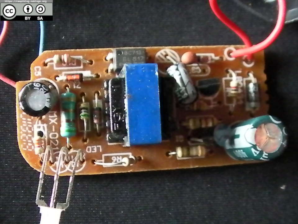
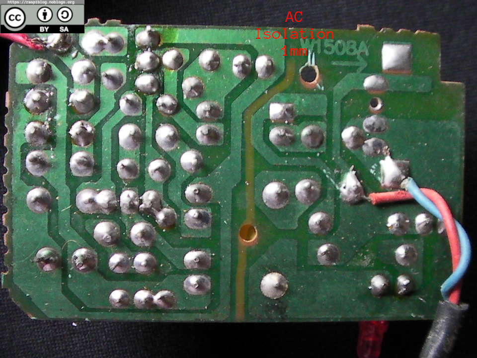
Here are the other adapters, with their PCB front and back. Soon to be reverse engineered.
They are dangerous because of the 1mm isolation from the mains. I will not use them.
Except where otherwise noted, this work is licensed under Creative Commons Attribution-ShareAlike 4.0 International License (http://creativecommons.org/licenses/by-sa/4.0/).
I hope that this post is useful to you, if you liked this post you may support me via liberapay. Thank you for your support.

Related: