WARNING:
In this project, We will be dealing with the AC MAINS which can kill you instantly. Observe proper procedures and precautions when dealing with the mains’ electricity.
1. Make sure you removed all your metal jewelries that can accidentally come in contact with the live(hot) or neutral wire.
2. Use only your one hand, preferably wear an insulated glove when dealing with AC mains, put your other hand at your back, so if you accidentally touched the mains it will not flow in to your chest cavity.
3. Always get another person observing you if you are dealing with the mains.
4. Anything above 12V can shock you and 0.50A of current can stop your heartbeat.
CAUTION:
Electrostatic Discharge (ESD)
All microcontroller and digital Integrated Circuit devices are sensitive to ESD, they may be destroyed by it instantly. Before unboxing or removing them in protective anti-static packaging, please ground yourself to a metal chassis or doorknob or wear an anti-static gloves.
I have found two good quality switching power supplies (adapters), one from a Philips GoGear Vibe adapter and another from my Cheap Chinese Polaroid Android Tablet adapter.
Philips SMPS:
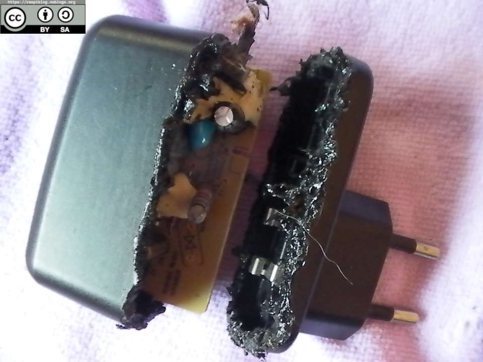
I had trouble opening the philips adapter since it does not have any screw, so I tried to melt the plastic using a soldering iron with a damaged tip. The process took me about 20-minutes or so.


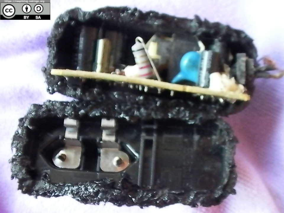
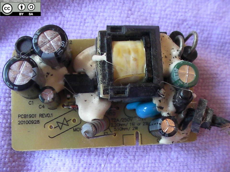
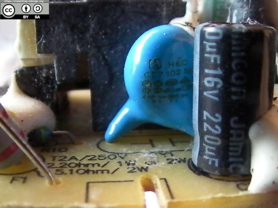
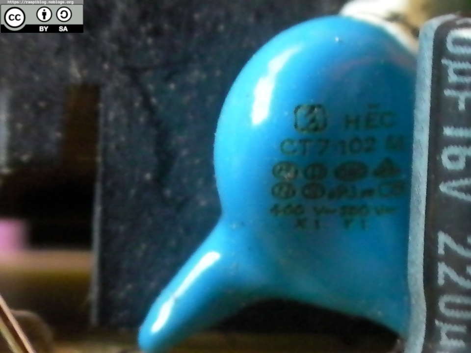
Upon opening the case, I was amazed by the PCB since it is of good quality. The AC input has a resistor (2.2 phm 1W) that protects it from inrush current, the PCB has a marking for a MOV but it was omitted. The board has a Class Y1 safety capacitor.
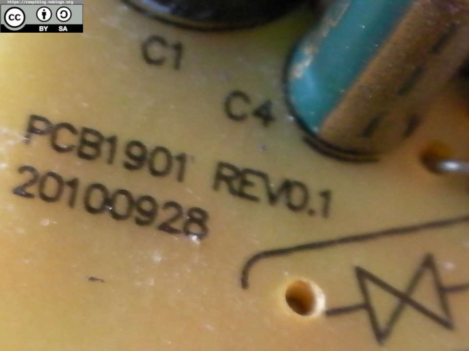
At the back of it, the board has a good main’s isolation from the DC output side, about 5mm between the AC (Primary) and DC (Secondary) side. There is also a marking of UL certification (E314348) and many SMD components.

The output voltage is 5.9V which is greater than the nominal 5V required for the nodemcu/wemos ESP8266 and Raspberry Pi, I need to use a voltage regulator that does not have a 1V dropout voltage. Possible solution are:
1. Use three 1N4007 diode in series to drop the voltage down to 5V, a diode drops 0.3V volts.
A single 1N4007 diode drops 0.3V.
Vout = (5.9V)-[(3)(0.3)]
Vout = 5V
2. Use a resistor to drop the voltage.
Ohm’s Law
Ro = (Vin - Vout)/Ia
Vin = 5.9V
Vout = 5V
Ia = 1.5A
Ro = 0.6 ohm
Power rating of the resistor:
P = VI
P = (5.9V-5V)(1.5A)
P = 1.35 W (For safety use a 2W resistor)
There is no 0.6-ohm resistor, so you need to connect two 1-ohm resistor in parallel to get the 0.5-ohm required value.
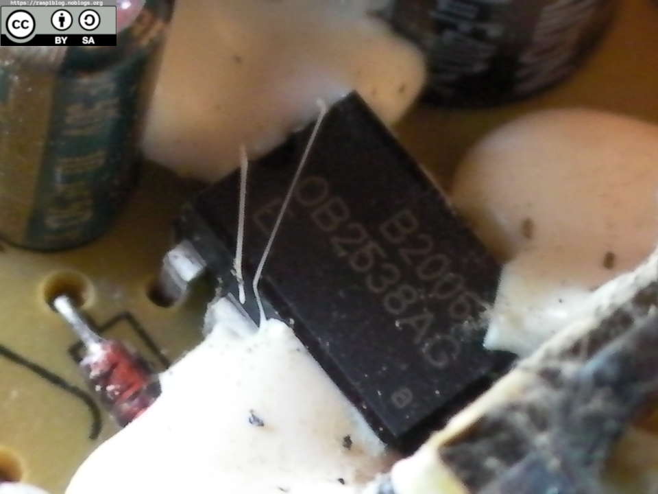
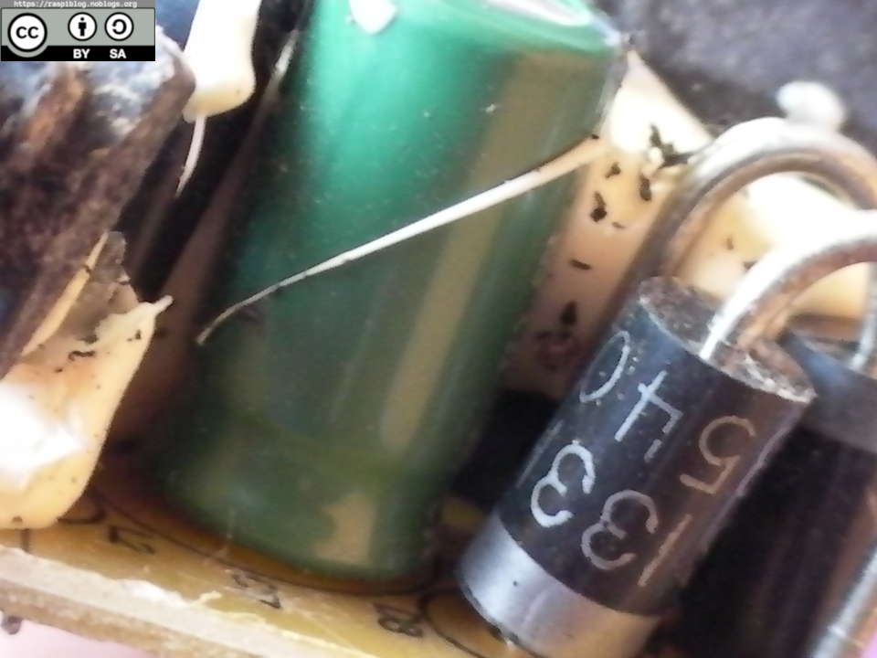
Polaroid Chinese Adapter (LA-520H)
I have reverse engineered the board, and you can download it below:
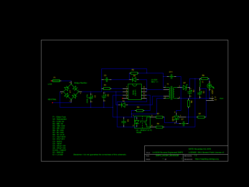
Disclaimer: I do not guarantee the correctness of the schematics.
The board has a Fuse that is covered with heat shrink, it does not have any inrush current protection or MOV.
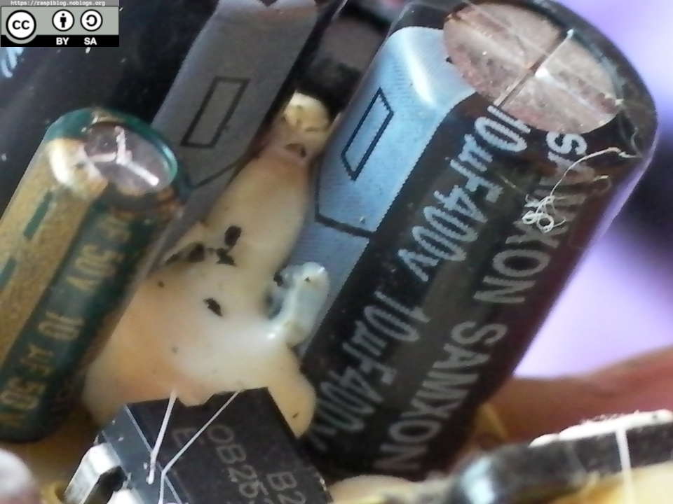
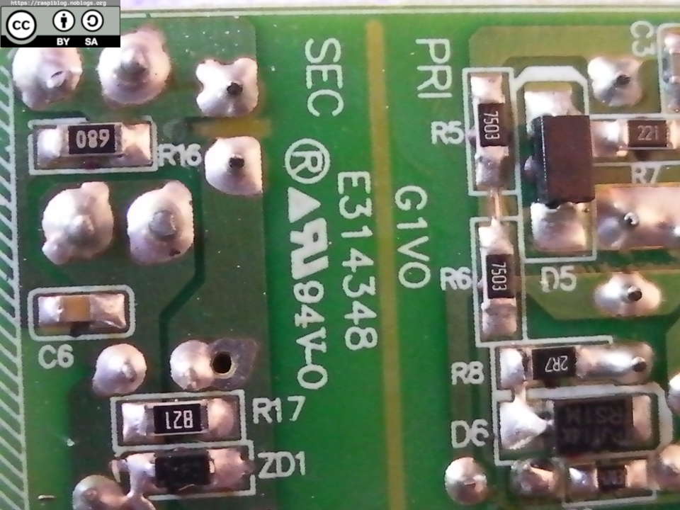
It has a class Y1 capacitor, and Chinese capacitors. At the back there is no SMD components but there is a good isolation between the Primary and Seconday side of the circuit, it is about 7mm.
The output voltage is at 5.4V which will potentially damage the Wemos D1 mini since it has a 5.5V Absolute maximum rating of the onboard DC regulator, so I used a single 1N4007 in series to the V+ of the board to reduce the voltage down to 5.1V.
I used this adapter to power the wemos d1 mini and relay (https://raspiblog.noblogs.org/post/2018/10/25/wemos-d1-mini-wifi-and-temperature-controlled-ac-outlet/)
More information on that post.
Except where otherwise noted, this work is licensed under Creative Commons Attribution-ShareAlike 4.0 International License (http://creativecommons.org/licenses/by-sa/4.0/).
I hope that this post is useful to you, if you liked this post you may support me via liberapay. Thank you for your support.
