ATtiny85 Li-Ion 18650 Battery Capacity Meter
I have many 18650 batteries salvaged from electronic gadgets, the problem is their capacity is either fake or not indicated (in the case of salvaged laptop battery or powerbank battery).
I made this battery capacity meter to measure the real capacity of a battery, but it is not accurate since I am not using a more advanced setup (shunt resistor).
This is inspired by danyk.cz Battery Capacity Tester
HARDWARE PART
The parts needed are:
– LCD 1602 with PCF8574 I2C Module

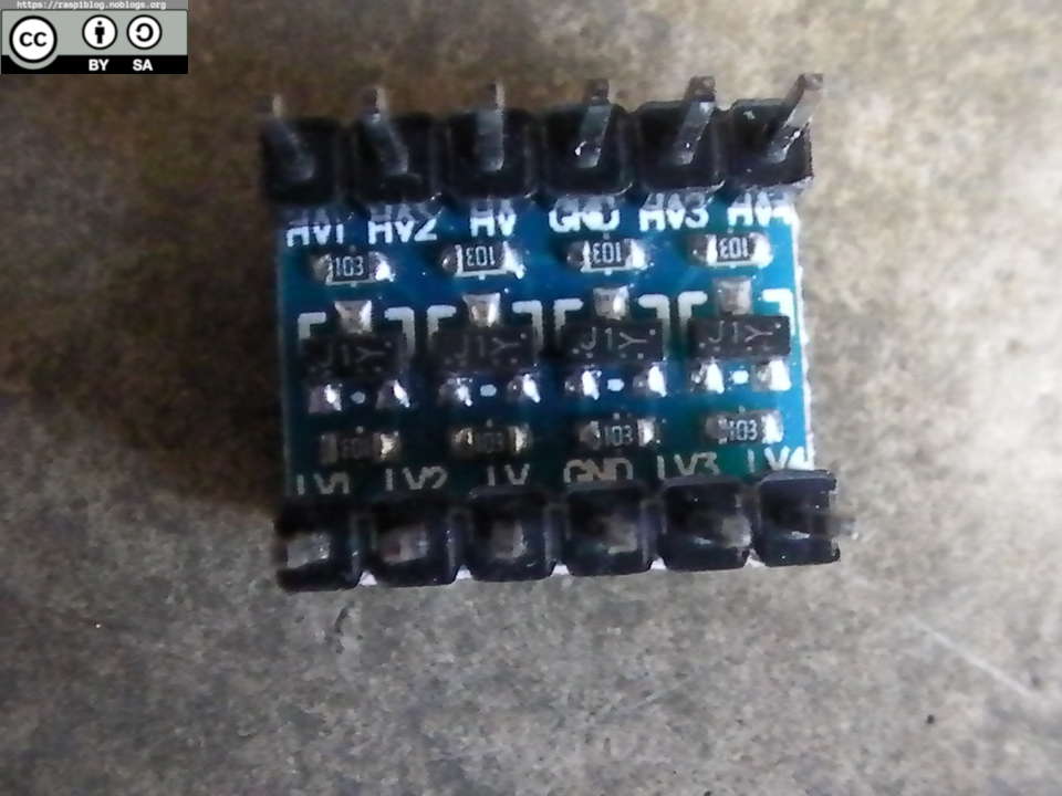
– I2C Bi-Directional Logic Level Converter Module

– ATtiny85
– ISP AVR programmer for ATtiny (or just use a Beaglebone/Raspberry Pi to program the ATtiny)
– NTD5867 N-Channel MOSFET (or any other similar)
– AMS1117-3.3V (or any better low dropout regulator like MCP1700/HT7533)
– IC Socket (8 pin)
– PCB prototype board (stripboard)
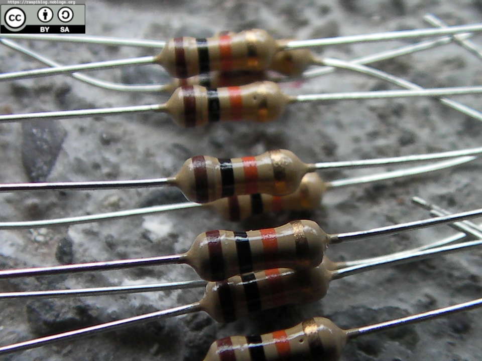
– 10K resistors
– Solid Wire jumper
– Jumper Header Female/Male
– Jumper wire (female to female/male to female)
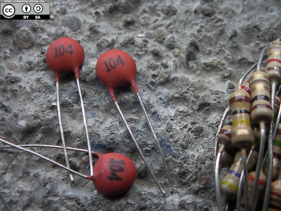
– Decoupling capacitors (0.1uF)
– 10 Ohm 10 Watt resistor
– 20 Ohm 10 Watt resistor
– USB Male connector
– Alligator clip (2x)
– Multimeter
– Soldering Iron
– Soldering Lead
– Flux
Software:
– Arduino IDE
– For the programmer, I used avrdude.
– LCD library (https://github.com/SpenceKonde/LiquidCrystal_I2C_Tiny)
– TinyWireM Library (https://github.com/SpenceKonde/TinyWireM)
Computations:
I need to create a load of atleast 0.5 A, I used 2 Resistors in parallel (10 Ohm 10 Watt and 20 Ohm 10 Watt)
R1 = 10 ohm
R2 = 20 ohm
RT = 1/[(1/R1)+(1/R2)]
RT = 6.677 ohm
Total Resistance is 6.667 ohm
Using Ohm’s Law:
V = IR
I = V/R
Il = (3.7V/6.667ohm)
Il = 0.55 A
Load current is 0.55 A
We can compute the battery capacity by measuring the load current multiplied by time.
The schematic can be found here:
attiny85-batt-capacity-18650.pdf
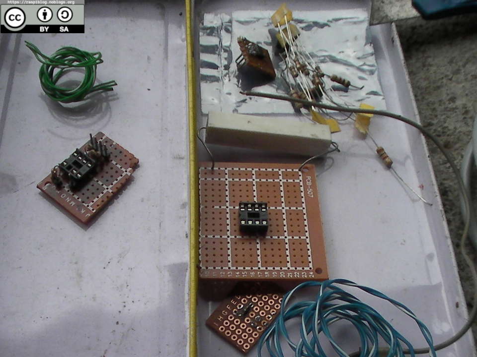
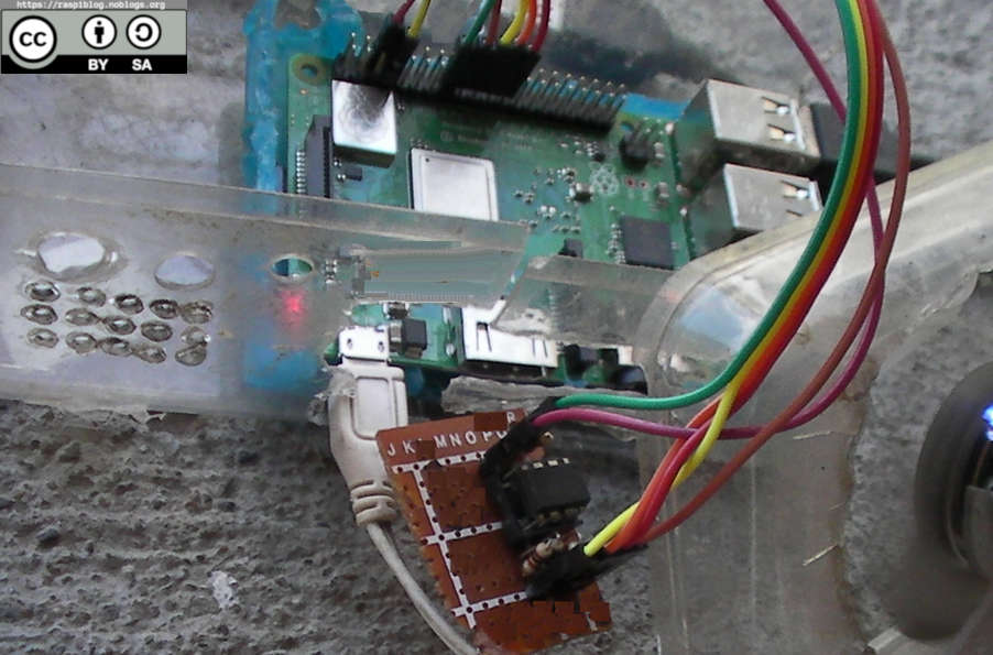
Prototype:
Here are the PCB parts.
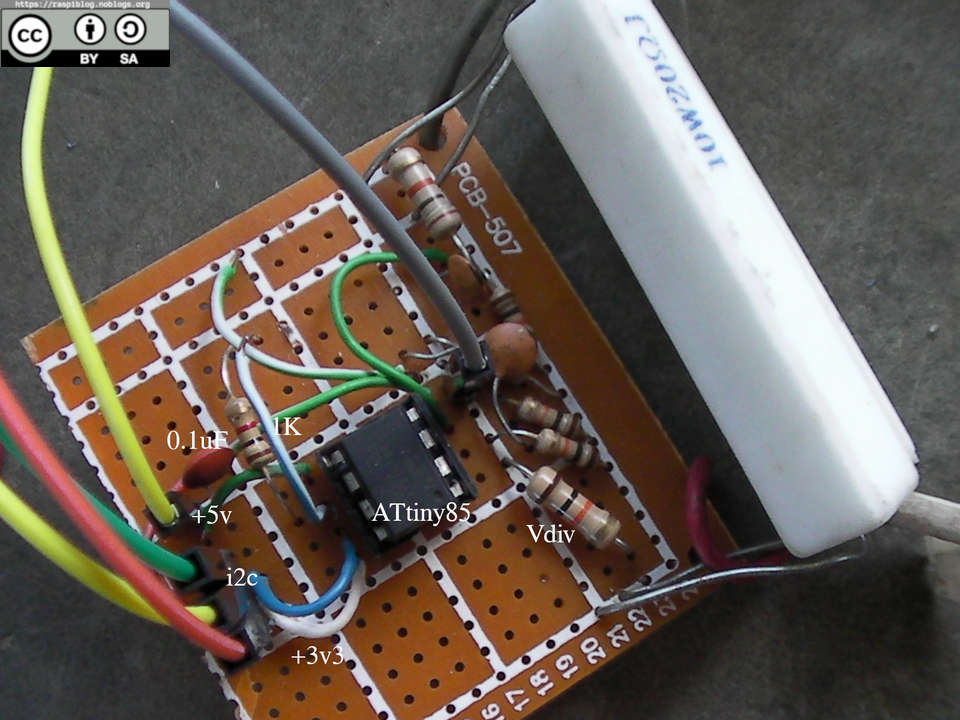
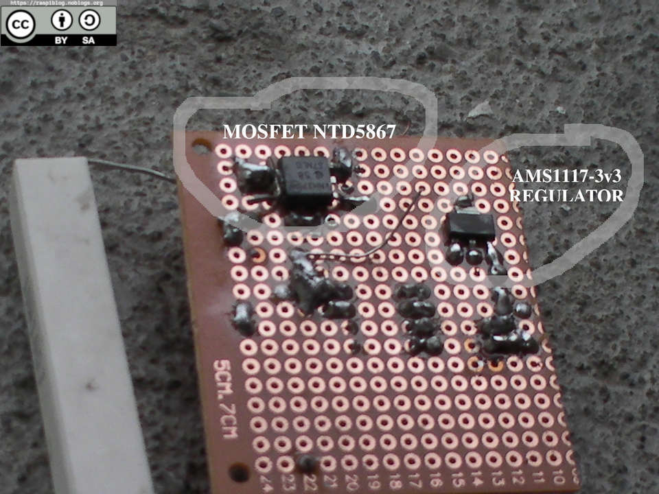
I have mounted SMD components at the back of the stripboard.
SOFTWARE PART
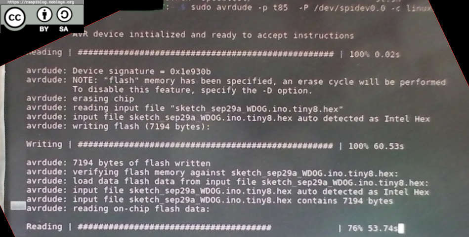
Compiling the code, I used the Arduino IDE to generate a binary file to be flashed on the ATtiny85 using a Raspberry Pi SBC.
You need to download the board definitions for ATtiny chips on Arduino IDE.
Set the board to ATtiny85, Clock to Internal 8 Mhz and Export Compiled Binary
Upload the binary file to Raspberry Pi and flash it
I followed this tutorial on flashing the ATtiny85 using Raspberry Pi:
https://www.instructables.com/id/Programming-the-ATtiny85-from-Raspberry-Pi/
The Raspberry Pi and my IC socket board for flashing
You must enable SPI for this to work. I used BCM22 (Board numbering not Pin numbering.)
$ sudo raspi-config

$ sudo gpio -g mode 22 out
$ sudo gpio -g write 22 0
$ sudo avrdude -p t85 -P /dev/spidev0.0 -c linuxspi -b 10000

$ sudo avrdude -p t85 -e  -P /dev/spidev0.0 -c linuxspi -b 1000 -U flash:w:sketch_attiny85_batt_capacity.ino.tiny8.hex
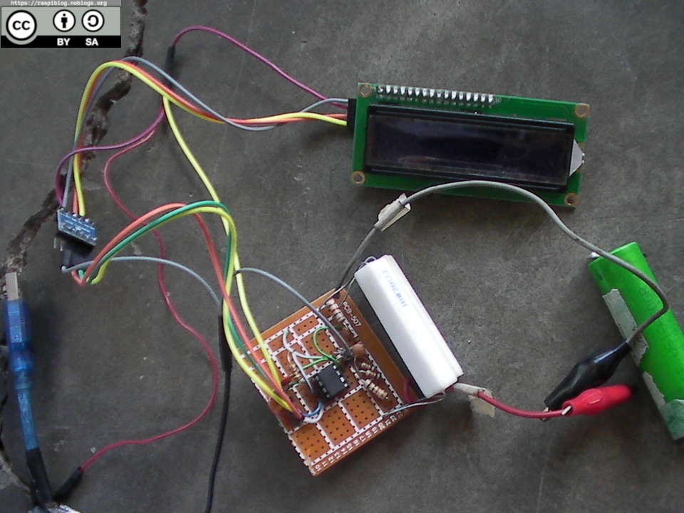
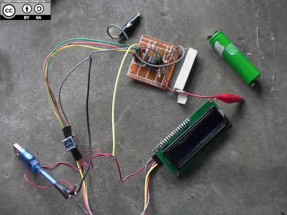
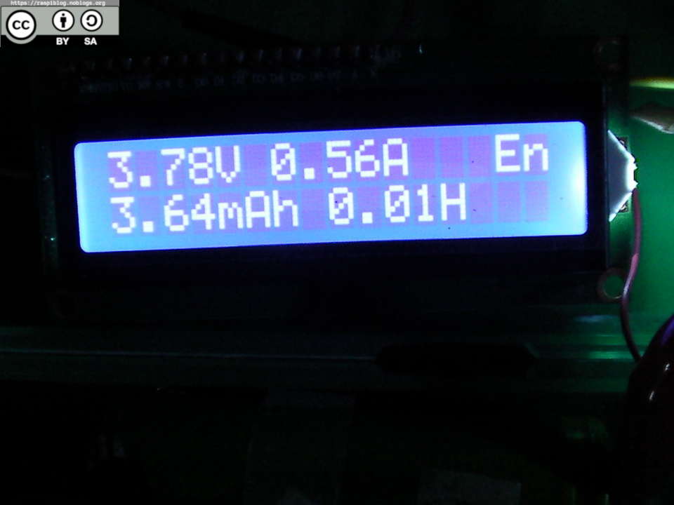
We can now test the project. Power it using a 5V supply (AC/DC SMPS or Powerbank). If you do not connect any batteries it should say “NO BAT !”, otherwise it should display the battery voltage, current, mAh and time plus “En”, if the battery is below 2.8V it will
turn off the MOSFET (cutting the load) and displays “BAT LOW !” with the total mAh indicated. It will halt for 30 minutes and clear the screen.

The program code will be uploaded soon.
Except where otherwise noted, this work is licensed under Creative Commons Attribution-ShareAlike 4.0 International License (http://creativecommons.org/licenses/by-sa/4.0/).
I hope that this post is useful to you, if you liked this post you may support me via Patreon or liberapay. Thank you for your support.