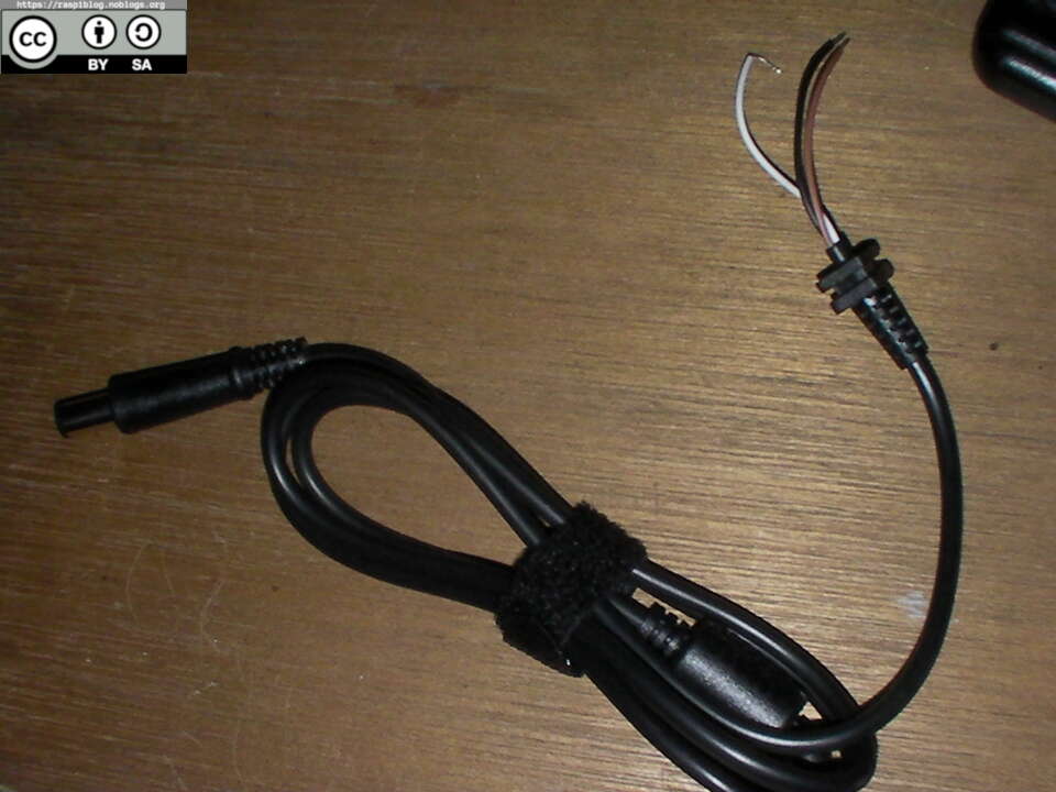
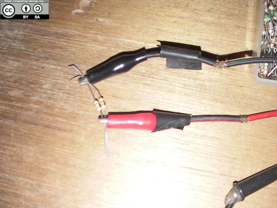
My Shopee order arrived today and it was the last thing needed to complete the DIY UPS for the HP T610. The order that arrived was a HP DC Jack 7.4×5.0mm with center pin, it is a replacement cord for the HP/Dell adapter. I already have the DC 6A 150W Boost/Step up Converter module a week ago and now it is time to create the circuit. According to this Parkytowers article, the center pin needs to be connected to the positive 19.5V with a 330K or 240K resistor. But the problem is I don’t have those resistors, (I may have them but I’m being lazy), I just used two 470K resistors in parallel to create a 235K resistance. I also measured the resistance between the center pin and positive 19.5V from the original HP Charger that I have and the result was 360K, this could be true but my multimeter is not behaving correctly recently. I used 22 AWG wire to power the Boost converter and I did not solder the resistor to the center wire connection but just taped it with masking tape. I’ve been running low on supply of electrical tape and other stuff since the lockdown. It worked and I did some stress-ng stress teswt and it seemed stable, the heatsink of the DC boost converter is not too hot to touch, it will be ventilated inside the casing though.
The sealed order, without bubble wrap:
Two 470K resistors in parallel:
Cable ready to be plugged in to the Boost converter nodule:
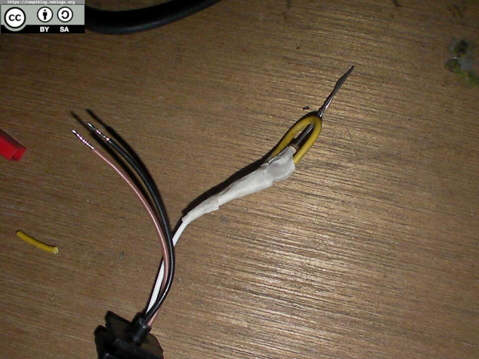
The white wire is the centern pin wire, it must be connected to the +19.5V output from the boost converter.
The brown wire is the +19.5V output, or whatever your output voltage will be.
The black wire is the common/ground wire.
The DC boost converter ready to be used:
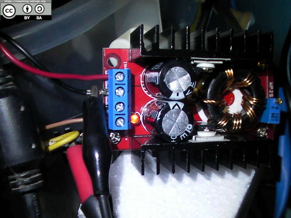
Solar charge controller (this acts like a UPS):
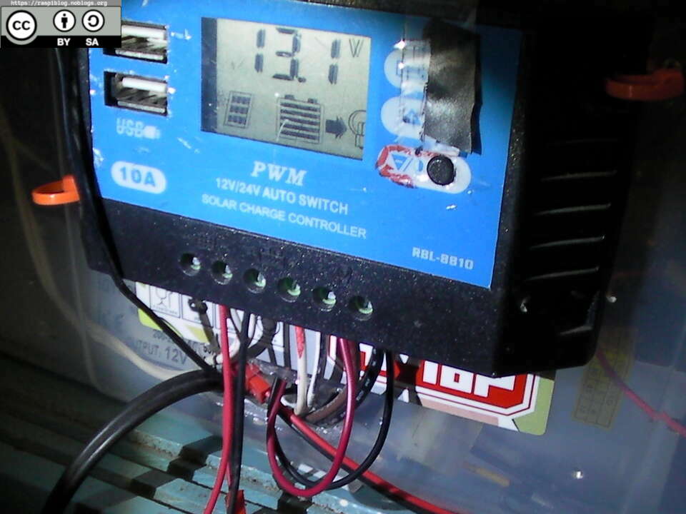
Another view of the input and output, the wire that I used is smaller in gauge and the reason is I don’t have any more wires. I just use what I can from old electronics:
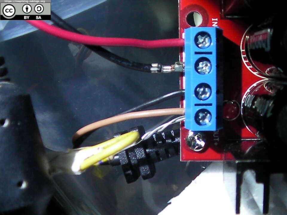
Plugged in cable from the DC Boost Converter Module
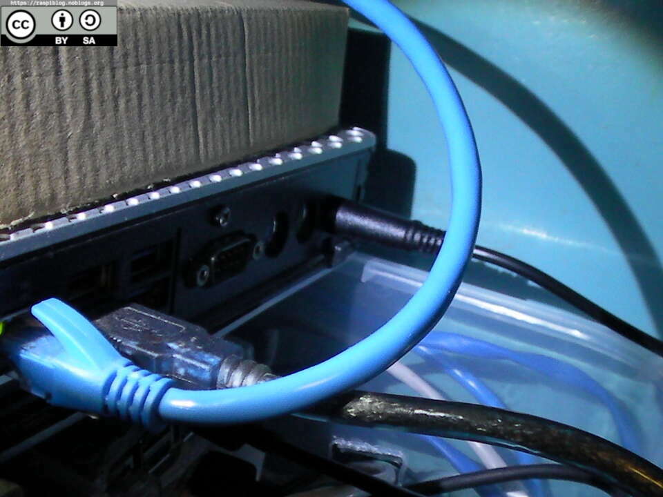
I don’t have an oscilloscope, so I cannot test whether the module produces any kind of voltage spike that may harm the HP T610, if you have experiences with this module please contact me or comment on my Youtube channel.
I will upload schematics later.
